Tig welding tips, questions, equipment, applications, instructions, techniques, tig welding machines, troubleshooting tig welding process
User avatar
  • Posts:
  • Joined:
    Thu Jan 24, 2013 6:44 am

paul_s
  • Posts:
  • Joined:
    Thu Feb 06, 2014 10:04 pm
  • Location:
    SW Florida

Love the flower.
User avatar
  • Posts:
  • Joined:
    Thu Jan 06, 2011 11:40 pm
  • Location:
    Near New Orleans

Otto Nobedder wrote:
MinnesotaDave wrote:Steve S. - I am wondering under what circumstances a leak that small would be an issue?

It seems like it would be too small to cause problems? What is the reasoning please?

Btw, I checked your math and agree with your findings. I had to check it since it was an astonishingly small leak and I was curious if it was true - lol :D
LOL! Good on you for checking the math! It DOES sound odd talking about cubic nanometers of helium!

The point of repairing even something this small is because it always grows over time. Once the crack grows beyond the weld it started in, it can leak fast, eliminating the vacuum on the vessel. (Think HUGE thermos bottle, with very cold liquid inside.) A loss of vacuum on the road causes a boil-out of that liquid to gas, potentially dangerous depending on the liquid, and always expensive in the best of cases. A failure that threatened life and property would cost far more than making repairs as needed. Replacement cost on these vessels is about $2.5-$3 million with a two-year lead time, so repairs and PM are cost-effective.

Steve S
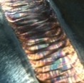
Here's a doozie, and only one of four leaks I've found so far (the most interesting one, aestheticly), and what happens when these things go undiscovered...
GEDC1309.JPG
GEDC1309.JPG (138.91 KiB) Viewed 2251 times
Steve S
RichardH
  • Posts:
  • Joined:
    Sun Jan 12, 2014 10:45 pm
  • Location:
    Chandler, Arizona, USA

SBblacksmith wrote:This is a front door that I made a little while back. Stainless steel frame with silicon bronze panels welded to the frame.

Finally got the picture upright.
That's a pretty big gun-port on the door. ;-)

My neighbor recently had a custom steel entrance door installed. I'm envious; it's nice and solid. But as much as I like it, I realize that with 13 large windows on my house fortifying the front door probably isn't worth it.

As a photographer, I really like the second pic of you working on the frame.

Cheers,
Richard
Grinding discs... still my #1 consumable!
danielbuck
  • Posts:
  • Joined:
    Tue Jan 21, 2014 7:56 pm
  • Location:
    Gilroy, CA

welding up some new body mounts for my TJ jeep (laser cut and pre-bent from SWAG Offroad), 1/4" thick, and boxed with nice sliding angles. MUCH stronger than the factory mounts, un-boxed and probably 1/8" thick, and not angled well to slide off of rocks. Most of them are folding over and bent real good from hitting bolders.

Anyway, since I have 6 of them to do, I figured I'd try different welding techniques on them all. I've done 3 so far, first was Flux core, 2nd was MIG, and 3rd is TIG. The flux core while it's penetrated well, isn't much to look at. The MIG to me looks just fine. The TIG could use work on consistency with the pedal and torch movement. First time TIGing with 220 power, I didn't have any filler rods larger than 1/16", I think a thicker filler rod would really help with the now higher power.

TIG is still new to me, so I think I'll do the rest of them with the TIG machine to get more practice. And then when it comes time to weld them onto the frame of the jeep in the driveway, I'll probably MIG them if the wind isn't bad. if wind is bad, I'll hit them with flux core wire. Can't fit a jeep in my garage anymore :lol:


Image

Image

Image
aeroplain
  • Posts:
  • Joined:
    Tue Jun 03, 2014 10:15 pm
  • Location:
    Minnesota

I weld alum mostly, but my boss needs me to do Stainless from time to time. This boat rail had studs and needed Feet.
Cut from plate with a hole saw, cleaned up and added to rail; boy!, do I need practice on stainless. Any way, it turned out "acceptable for what it was.
Image
Image
Image

Image
SBblacksmith
  • Posts:
  • Joined:
    Tue Oct 22, 2013 4:51 pm
  • Location:
    Santa Barbara

This is a handrail that I am working on. 1 1/2 sch 80 with 1 1/2 .120 wall tube running through. The whole thing has set screws that lock it together
Attachments
image.jpg
image.jpg (39.81 KiB) Viewed 2318 times
image.jpg
image.jpg (60.73 KiB) Viewed 2318 times
image.jpg
image.jpg (61.98 KiB) Viewed 2318 times
Famous last words, "Hey guys, watch this!"

Www.SBForge.com
aeroplain
  • Posts:
  • Joined:
    Tue Jun 03, 2014 10:15 pm
  • Location:
    Minnesota

Made this small tank today for a bicycle that a guy I know is fitting with a 49cc engine. .050 5000 series, filler neck is unknown thickness 6061. Bends made in the Vise.


Image
User avatar
  • Posts:
  • Joined:
    Thu Jan 24, 2013 10:13 pm
  • Location:
    Eddy, TX

aeroplain,
Looks like a fun fuel tank project! I am in the middle of some fuel tanks, although not as fancy as yours, will get pics up when I get further along.
-Jonathan
aeroplain
  • Posts:
  • Joined:
    Tue Jun 03, 2014 10:15 pm
  • Location:
    Minnesota

Thanks, it was fun. It oughta look cool on the "Tall bike" the kid built using vintage bikes.
Kent
Superiorwelding wrote:aeroplain,
Looks like a fun fuel tank project! I am in the middle of some fuel tanks, although not as fancy as yours, will get pics up when I get further along.
-Jonathan
User avatar
  • Posts:
  • Joined:
    Sun Oct 27, 2013 8:58 am
  • Location:
    Cape Cod, MA

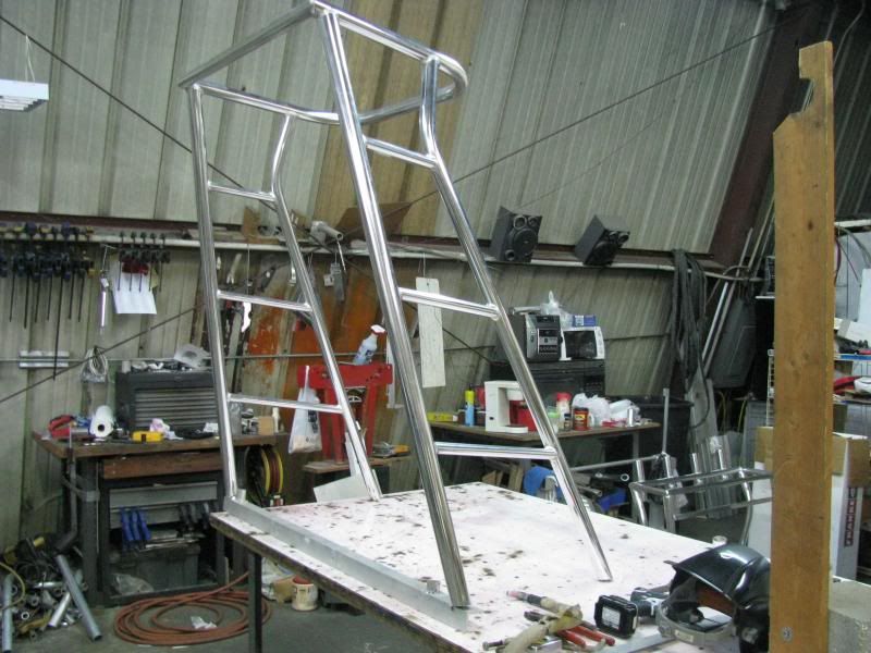
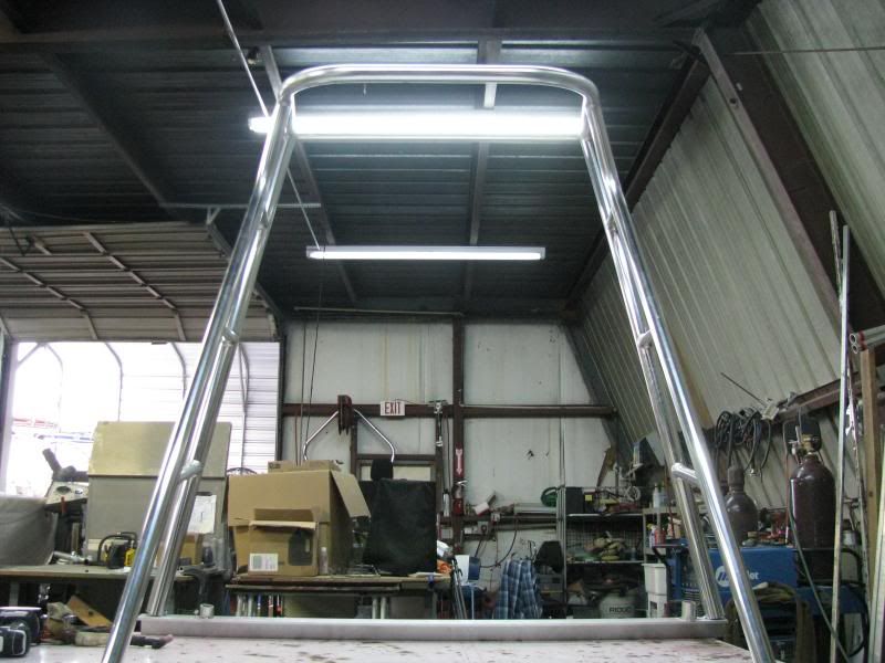
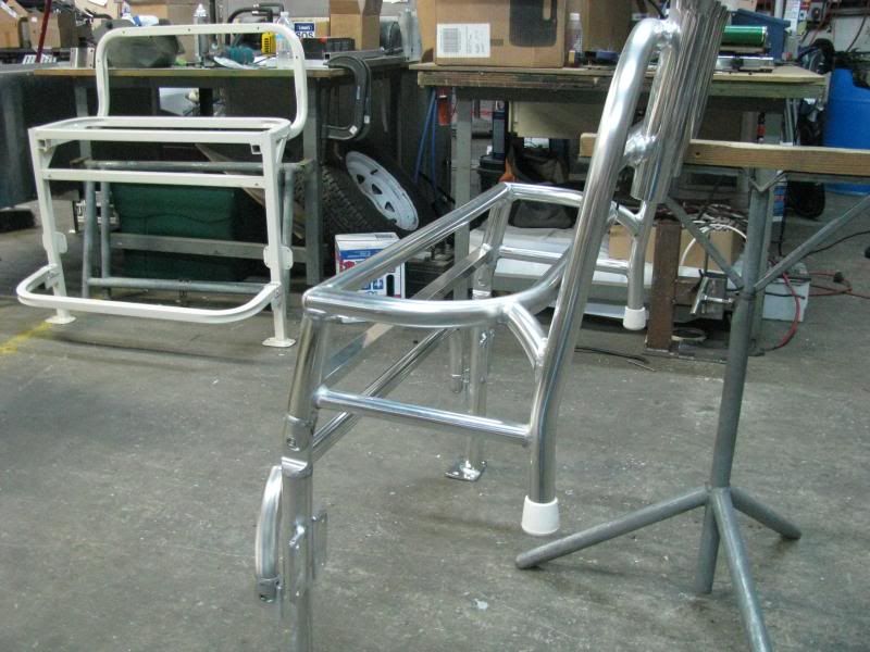
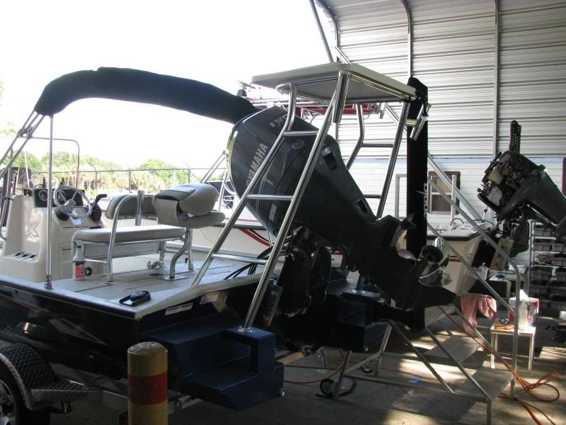
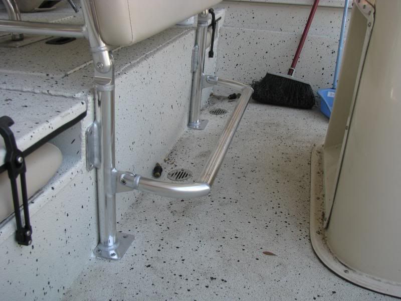
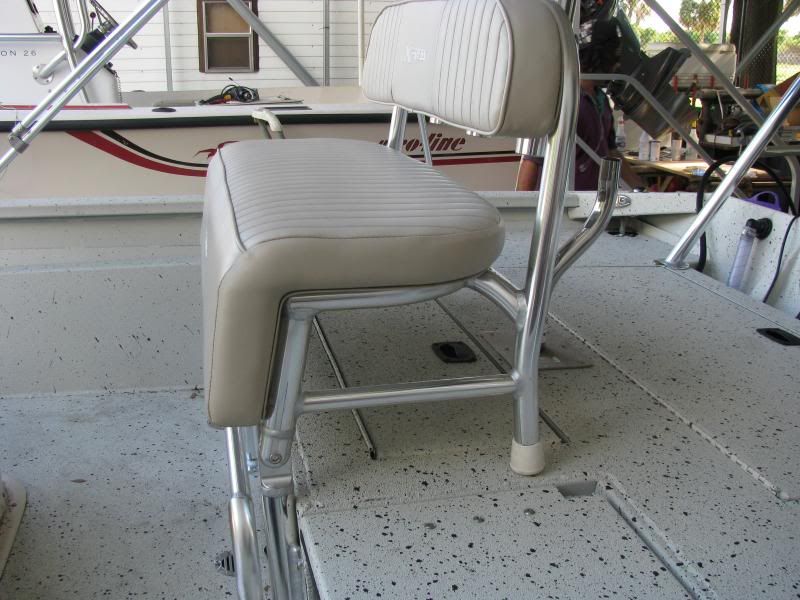
aeroplain wrote:I weld alum mostly, but my boss needs me to do Stainless from time to time. This boat rail had studs and needed Feet.
Cut from plate with a hole saw, cleaned up and added to rail; boy!, do I need practice on stainless. Any way, it turned out "acceptable for what it was.
Image
Image
Image

Image

What and howdid you polosh your welds. Great job.
Best regards,
Geoff C
http://www.gscmarine.com
Miller dynasty 200 DX
Hobart Handler 140
aeroplain
  • Posts:
  • Joined:
    Tue Jun 03, 2014 10:15 pm
  • Location:
    Minnesota

What and how did you polish your welds. Great job.
"Perfect-it"#1 polishing compound and a buffer (wool pad). Seems to clean easily.
aeroplain
  • Posts:
  • Joined:
    Tue Jun 03, 2014 10:15 pm
  • Location:
    Minnesota

I work in boat repair, so welding is only a small part of my job. All the dust and paint over-spray makes for a challenging environment when I do get to weld. Nothing is ever clean, rarely on the bench, and out of position can be an understatement. The first time I ever TIG'ed was on my belly, arms out stretched, in a Sump Well to fix cracks on some knee braces (Alum). Hope the guys boat still floatin. :oops: My point is, that not much of my welding looks pretty IMO, but it's strong and I'm confident now some years later after that first go. Thanks to guys like Jody and the rest of you guys here!!

Cast sucks!
Image
Image
Image
Image
Image
User avatar
  • Posts:
  • Joined:
    Thu Jan 24, 2013 10:13 pm
  • Location:
    Eddy, TX

Well the finished product looks very nice. On the inside weld you need a little more amps to wet it in a little better. I do agree, it will (should) hold.
-Jonathan
TamJeff
  • Posts:
  • Joined:
    Tue Dec 04, 2012 4:46 am

I'll toss in a couple. Perhaps a little redundant but, somewhat interesting engineering at least.

Extra tall poling platform.
Image

Sides had to lean in 10 degrees, so I had to articulate the oval step treads accordingly. You would be surprised how many people don't bother with such mediocre details.
Image

Also made him a new chair to replace the crappy factory jobby that is showing in the photo. I should have taken pictures of the squirt welds on that to post here. I made this one flip up. so he could at least get to the live well that the factory chair covered. No kidding. You could not open the hatch to the live well!
Image

Coming round.
Image

With a nicer footrest and you can see the joints that make all this possible. They have nylon friction washers and you can tighten them to whatever tension you desire. It will stay up in any position.
Image

The bastard being, I had to reuse his upholstery. Had to lean the top of the legs back 10 degrees so that it doesn't pitch-pole you out of the seat if you dare move. Can also see the live well under it that he can now use. :)
Image
Miller ABP 330, Syncrowave 250, Dynasty 300 DX.
Honorary member of the Fraternity of Faded Tee Shirts.
aeroplain
  • Posts:
  • Joined:
    Tue Jun 03, 2014 10:15 pm
  • Location:
    Minnesota

That's really nice work! It's not redundant to me, I just got here. :D
I assume a squirt weld is the technique I've only heard of when welding anodizing?
TamJeff
  • Posts:
  • Joined:
    Tue Dec 04, 2012 4:46 am

That painted chair across from the one I just built. There is welds on it so bad, it defies any sense of logic. They squirted welds on there with what 'looks' to be from some sort of Alu-mig. . .yet the joints are still open. As if a blind/drunk person welded them and missed the joint entirely or just gave up. There are others that are so cold and overlapped, that paint couldn't get behind them.
Miller ABP 330, Syncrowave 250, Dynasty 300 DX.
Honorary member of the Fraternity of Faded Tee Shirts.
gamble
  • Posts:
  • Joined:
    Mon Mar 07, 2011 1:10 pm

Image
1/4" 1018 steel
3/32 filler
about 200 amps
3/32 red tungsten
newschoppafowah
  • Posts:
  • Joined:
    Wed Feb 19, 2014 11:54 pm

I had a serious case of hammer looking for a nail disease, so I made a fake engine for my bicycle.

To try and learn something, I made it a varying thickness aluminum exercise.
.040 sheet
1" sch 40 PIPE
1" .059 TUBE
2" sch 40 PIPE
3/8" TUBE

It's all 6061 T6 except the 3/8 which is 6063 T5
I'll have to figure out a classier mounting situation, but for today electrical tape gets it in the done pile.
Attachments
use this one.JPG
use this one.JPG (52.18 KiB) Viewed 2126 times
Sent from an earthen ditch outside Needles, CA using an awful lot of low voltage single strand wire.

It's a matter of flour and water and then there's the seasonings, which is a matter of salt and so forth and then you h-we interrupt this for the announc
User avatar
  • Posts:
  • Joined:
    Thu Jan 06, 2011 11:40 pm
  • Location:
    Near New Orleans

Today's (and next week's) adventure is to replace a 1" sch. 160 pipe with a 3/4" sch. 160 pipe. Seems the 1" isn't rated for 10Kpsi, so I'm fixing an engineering boo-boo. I enjoy the small-bore stuff. This time, it's 10% x-ray required, though they'll probably shoot 7 of 35 welds, for 20%

Here's a bit of bench-top pipe fitting on one segment. I love benchwork and roll-outs!
GEDC1335.JPG
GEDC1335.JPG (185.97 KiB) Viewed 2085 times
And here it is tacked,
GEDC1338.JPG
GEDC1338.JPG (182.37 KiB) Viewed 2085 times
And with the second pass on. Good shot of a capped weld, too. By the time this is done, maybe I'll be back to having consistent-looking welds.
GEDC1339.JPG
GEDC1339.JPG (173.73 KiB) Viewed 2085 times
All in all, a pretty good day, welding at the bench. I have another, bigger segment to start Monday, but will have very few welds "in position", so the x-ray shouldn't be so stressful as last time.

Steve S
User avatar
  • Posts:
  • Joined:
    Thu Jan 06, 2011 11:40 pm
  • Location:
    Near New Orleans

BTW, every bit of that 304SS is "Made in USA", and I can tell the difference!

Steve S
aeroplain
  • Posts:
  • Joined:
    Tue Jun 03, 2014 10:15 pm
  • Location:
    Minnesota

Nice looking Steve, it's part of why I hang around; to see what to shoot for. 8-)
User avatar
  • Posts:
  • Joined:
    Thu Jan 06, 2011 11:40 pm
  • Location:
    Near New Orleans

Anyone notice the HAZ is shorter on the ell than on the pipe? And oddly shaped, since the pipe side HAZ is almost dead-straight?

I'll have to get an end-view of the ell to explain it, but the mandrel it's bent on has a smaller (and odd-shaped) ID than the pipe, and the ends of the ell are back-beveled to a matching ID to the pipe... Short form, there's more mass in cross-section in the ell, so, smaller HAZ.

Steve S
User avatar
  • Posts:
  • Joined:
    Thu Jan 24, 2013 10:13 pm
  • Location:
    Eddy, TX

Otto Nobedder wrote:Anyone notice the HAZ is shorter on the ell than on the pipe? And oddly shaped, since the pipe side HAZ is almost dead-straight?

I'll have to get an end-view of the ell to explain it, but the mandrel it's bent on has a smaller (and odd-shaped) ID than the pipe, and the ends of the ell are back-beveled to a matching ID to the pipe... Short form, there's more mass in cross-section in the ell, so, smaller HAZ.

Steve S
Great job! I love to see how others lay out their projects. If I remember right most elbows are smaller i.d. than the pipe. Isn't this because of the pressure rise in the transition of a 90? Very good catch on the HAZ. I haven't welded a elbow on in probably a year.
-Jonathan
User avatar
  • Posts:
  • Joined:
    Thu Jan 06, 2011 11:40 pm
  • Location:
    Near New Orleans

I'll make a point of getting a pic of the end of an ell on Monday, and you'll see what I mean about the odd shape. It has a cross-section in a "D" shape, with the flat of the "D" on the inside curve. Then a very short bevel to pipe ID. The HAZ seems to follow the variation in metal density, which is what I found interesting.

I haven't much experience butt-welding small-bore pipe under 2". I'm used to socket-welds for 3/4", so I'm paying attention, and learning new things as I go.

Steve S
Post Reply