So taking into account some of the advise I took another shot this time it was a butt plate I welded onto the tube so chromolly going onto good old cold rolled steel plate.
Use a 1/16 filler rod this time, same cup, tungsten and gas flow rates.
What is the rule of thumb for setting the flow meter, I just stick it at 15cfm for anything I weld under 200 amps.
Up it if the material gets thicker.
DSM8,
I was told when I started Tig welding (late 70's) that you should use around double what your cup size is, as in #8 = 16 cfh and #5 = 10 cfh. and it's always been fairly close for a starting point. I'm inherently cheap so I usually go down from there until things start to get ugly, then go up until I have a little buffer. Back then everybody used standard cups and minimal stick out and now most use a gas lens and more stick out but it still holds pretty true. That's what has worked for me.
Braehill wrote:DSM8,
I was told when I started Tig welding (late 70's) that you should use around double what your cup size is, as in #8 = 16 cfh and #5 = 10 cfh. and it's always been fairly close for a starting point. I'm inherently cheap so I usually go down from there until things start to get ugly, then go up until I have a little buffer. Back then everybody used standard cups and minimal stick out and now most use a gas lens and more stick out but it still holds pretty true. That's what has worked for me.
Len
I use a #8 with gas lens and have pretty much kept it at 15cfm for all my welding at this point.
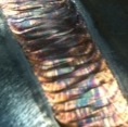
Oscar wrote:I see undercut in those last pics. Also,what are you doing to the weld heat to get them 100% silver? I see absolutely no heat tint what so ever.
Could you explain what you mean by undercut?
I am taking a stainless steel brush to the welds after they are completed. There is some contaminants on the pipe, I did not clean it as well as I should to shiny metal to I just removed the carbon smudges that were there with the wire brush to better show the welds.
Undercut = an underfilled groove along the top leg of the fillet weld, generally from running too hot for the travel speed and it doesn't get filled in, leaving an undercut groove in the base metal.
AWS D1.1:2010 Annex K defines undercut as: "a groove melted into the base metal adjacent to the weld toe or weld root and left unfilled by weld metal."
BTW, I'm not seeing the undercut that he mentioned.
John Wright AWS Certified Welding Inspector
NDT Level II UT, VT, MT and PT
NACE CIP Level I Coating Inspector
don't make it harder on yourself. practice on shiny bright metal. get the scale off. it always bums me out when i see guys making it harder on themselves when they are trying to learn/practice by not cleaning and prepping. get into the good habits early on. you will thank yourself later.
I am having a hard time telling if that is really undercut. Pic in a smartphone are not the best to look at. Since it was brought up and to satisfy our curiosity, can you verify or get another pic up? I (we) are not making fun of your weld or ability whatsoever.
-Jonathan
Superiorwelding wrote:I am having a hard time telling if that is really undercut. Pic in a smartphone are not the best to look at. Since it was brought up and to satisfy our curiosity, can you verify or get another pic up? I (we) are not making fun of your weld or ability whatsoever.
-Jonathan
Didnt take it as such, here is the original picture.
Here is the link to the gallery with the other pictures if you want to see all of them, they are the first 5 in the gallery.
Since we are on the subject of undercut...(just for the benefit of the OP and anyone else that is interested)
As a structural weld inspector, here is how I would visually check for undercut without the use of a v-wac gage that is used to measure undercut. It is a quick visual that I use to see if I even need to break out the v-wac gage....the use of shadows.
I would initially hold my flashlight *parallel* to the pipe shining down towards the weld and see if I see any shadow along the top toe of the weld, then do the same at the base plate to check along the bottom toe of the weld. If I do happen to see a shadow indicating undercut base metal, I can use the v-wac gage to measure the undercut and then apply the acceptance/rejection criteria listed in AWS D1.1:2010, Table 6.1, Item 7 A & B.(other codes have similar wording)
AWS D1.1:2010
(7) Undercut
(A) For material less than 1"[25mm] thick, undercut shall not exceed 1/32"[1mm], with the following exception: undercut shall not exceed 1/16"[2mm] for any accumulated length up to 2"[50mm] in any 12"[300mm]. For material equal to or greater than 1"[25mm] thick, undercut shall not exceed 1/16"[2mm] for any length of weld.
(B) In primary members, undercut shall be no more than 0.01"[0.25mm] deep when the weld is transverse to the tensile stress under any design loading condition. Undercut shall not be more than 1/32"[1mm] deep for all other cases.
Last edited by jwright650 on Thu Jan 08, 2015 6:35 pm, edited 1 time in total.
John Wright AWS Certified Welding Inspector
NDT Level II UT, VT, MT and PT
NACE CIP Level I Coating Inspector
Tonight I will weld the other side to another coupon of the same material, but this time both will be to shinny metal, wiped with acetone and sprinkled with holy water.
I will get the pics up this evening or tomorrow, I will even use a real camera for high resolution.
When I was learning tig, I had issues with undercut outside the weld pool, it would just appear right at the edge without reason (at the time) I believe it was an electrode angle thing. I don't know about you, but don't do drastic movements of the torch until youre down with it all.
My biggst issue is getting torch position maintained properly while going around the pipe.
The round shapes are the one I have done the least amount of practice with.
I still am not clear on this undercut, it is visible in any of the new pictures I have posted.
Righto. Get your self a number 8 or bigger cup. This will allow you to prop the bottom and maybe even the top of the cup on the job, like a the hypotenuse of a triangle. That will allow you to only concentrate on the travel angle and forward movement.
#8 with a gas lens is what I am using, tried calking the cup, and propping it with the electrode just slightly proud on the cups face.
That was much harder for me than having more stickout and having to keep the distance managed by hand.
Foot pedal.
Angle was 45 I did that intentionally to try and get the most consistent approach on the weld.
Was set at about 150 amps.
plate and tube are both 120 wall thickness, I had it set about 120 but it was not causing the puddle to form on the plate consistently so i upped it a bit to get it to flow better between the pipe and the plate.
Appretiate all the tips, I know teaching from a keyboard is not easy.
I just need to spend more time working on the pipe joint welding. This is only the third time I have welding this kind of joint