Tig welding tips, questions, equipment, applications, instructions, techniques, tig welding machines, troubleshooting tig welding process
brownthumb
  • Posts:
  • Joined:
    Thu Mar 26, 2015 2:28 pm

Hey guys... been lurking a while reading up on welders to buy. I finally bit the bullet and got an HTP Invertig 221. I wired it up and got started the other night. After two passes at the most basic settings, I was welding better than ever.

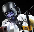
I have been welding Stainless, mild, and 4130 with my Miller Maxstar 140. Lift arc with no foot pedal, and thumb wheel gas valve.

Switching over was a little tricky. I keep wanting to touch the tungsten like on my miller to start the weld. haha...

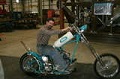
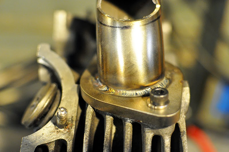
I own a small garage motorcycle company and make intake manifolds, exhausts, handlebars, as well as seats and some frame parts. I had a individual intake manifold to make so i figured i would give the HTP its first paying job.

These are 16 gauge 304 stainless tubing welded to mild steel 1/4" flanges. I used a 2% thoriated tungsten 1/16, with a smaller gas lens... No back purging.

The welds came out ok. Im still a little shaky with this machine but its coming together. This was at pretty high amperage... close to 100amp using DC pulse with 33%frequency 33duty and 33 background.

The welds seem a little cold to me. I got decent penetration, but i had to move way slower than i was used to. But i thought 100 amp was alot of juice. I also had the piece clamped to a aluminum 1" plate while i welded so quite a bit of heat gets drawn out through the bottom i think.

Just wanted some feedback... sorry for the long 1st post!

Cheers

Image
User avatar
  • Posts:
  • Joined:
    Thu Jan 06, 2011 11:40 pm
  • Location:
    Near New Orleans

That's pretty damn good for a first go with a new machine.

Steve S
User avatar
  • Posts:
  • Joined:
    Thu Dec 26, 2013 12:41 am
  • Location:
    Laredo, Tx

Do you routinely make intake manifolds out of steel? Most I seen are aluminum. :lol:

Good choice on the machine. The new "red"!
Image
User avatar
  • Posts:
  • Joined:
    Wed Aug 06, 2014 12:48 am
  • Location:
    Melbourne, Australia

Brownthumb, Great effort, clearly you're getting the hang of that machine from an early start.

Oh, and welcome aboard!

Trevor
EWM Phonenix 355 Pulse MIG set mainly for Aluminum, CIGWeld 300Amp AC/DC TIG, TRANSMIG S3C 300 Amp MIG, etc, etc
SmartDave
  • Posts:
  • Joined:
    Fri Dec 19, 2014 12:43 pm
  • Location:
    Bellingham, MA

I have that same machine, you will love it.


Sent from my iPad using Tapatalk HD
massacre
  • Posts:
  • Joined:
    Sat Feb 28, 2015 10:20 pm
  • Location:
    Massachusetts

Another happy HTP owner here, not to sound like a broken record but I also love my machine a ton, very happy with it's performance!
Your welds look great for first time. I haven't even used the pulse on mine yet lol!
soutthpaw
  • Posts:
  • Joined:
    Thu Sep 18, 2014 12:14 pm
  • Location:
    Sparks, NV

The guys I know doing a lot of stainless run a much faster pulse, usually. 60-150 pps. Might be worth trying once you get used to your new machine.
User avatar
  • Posts:
  • Joined:
    Thu Dec 26, 2013 12:41 am
  • Location:
    Laredo, Tx

100A is a lot of juice, but once you run it through the pulse funcion, the total amperage/heat input is "watered" down. Running through a 33% duty cycle/33% background current reduces the effective heat to 56% of what is "set" on the machine. Interesting to note, that the PPS doesn't change the heat reduction percentage once the duty cycle and background curent are already decided on, when actually calculated as "area under the curve". As PPS increases, the both the peaks and the dips are skinnier, contibuting less for each individual cycle, but there's more of them because there are more pulses in each second, for a net change of 0. :ugeek: Of course there's more to it when actually welding, because welding speed has to be taken into account.
Image
brownthumb
  • Posts:
  • Joined:
    Thu Mar 26, 2015 2:28 pm

Thanks for the responses...

Thats interesting that changing the pps doesnt reduce the heat intake of the metal... So its almost like the duty and background need to be set almost to the type of heat you want for the metal your welding...

I spent the day on friday just making these single manifolds... I think I settled on closer to 60%duty and 60% background with 33 pulse... With this i was running about 75 amps to get good penetration... With a 309 rod too... forgot that in the original post...

I have been planning on going to a full stainless flange and tube, but have to burn through my stock of mild steel flanges first... haha...

I feel like i made alot of progress this weekend... I still cant break the habit of lift arc though... haha... That and i tend to pull away the torch when im finished with a weld. I was welding with that lift arc Miller for about 3 years.... I think once i get used to this HTP and get a little more stable hand wise the welds will look much better...

Aluminum is in the future... haha...
User avatar
  • Posts:
  • Joined:
    Thu Dec 26, 2013 12:41 am
  • Location:
    Laredo, Tx

brownthumb wrote:Thats interesting that changing the pps doesnt reduce the heat intake of the metal... So its almost like the duty and background need to be set almost to the type of heat you want for the metal your welding...
.
Just to clarify, changing the PPS can change the heat input, but it's mainly a PPS-vs-travel-speed ratio kind of thing. If you really slow down the PPS, then you can and will overheat an area because you won't be advancing along the weld bead all that much while you're waiting for the low-current portion of the pulse. I won't bore you with ratio's and numbers and what-not, but once the PPS-to-travel_speed ratio passes a certain point, then more PPS alone won't reduce heat-input any further. It can however get you more arc-focus (by adjusting the peak amps, duty cycle, and/or base current) if doing a certain joint, like an inside-corner type thing requiring thick-to-thin fusion.
Image
brownthumb
  • Posts:
  • Joined:
    Thu Mar 26, 2015 2:28 pm

Yeah I still have to spend some time adjusting and playing with settings... gotta wrap my head around it all...

Spent some more time welding with the setup i have. I have a small gas lens on my torch, but i have medium and large pyrex cups in the mail...

I also ordered some SS flanges and 308 rod... Excited to do some stainless to stainless welding with this...

These were all SS to mild with 309... Getting a little steadier...

Image
User avatar
  • Posts:
  • Joined:
    Thu Dec 26, 2013 12:41 am
  • Location:
    Laredo, Tx

Look pretty good from here. Are you getting any warping on the flange?
Image
brownthumb
  • Posts:
  • Joined:
    Thu Mar 26, 2015 2:28 pm

The flanges are mild steel and i have them bolted to a mock up head to keep them flat. I think the trickiest part is getting enough heat in the weld before the aluminum head sucks it all out...

I have some stainless flanges coming, so ill post up some photos when i can weld some stainless to stainless with back purging...
User avatar
  • Posts:
  • Joined:
    Wed Aug 06, 2014 12:48 am
  • Location:
    Melbourne, Australia

Looking pretty good. Keep us posted!
EWM Phonenix 355 Pulse MIG set mainly for Aluminum, CIGWeld 300Amp AC/DC TIG, TRANSMIG S3C 300 Amp MIG, etc, etc
User avatar
  • Posts:
  • Joined:
    Thu Jan 06, 2011 11:40 pm
  • Location:
    Near New Orleans

Nice work,

And, whether you realize it or not, using an old aluminum head to bolt those flanges to is an excellent idea. The faster you can wick out any excess heat, the less distortion you will have in the finished product. You can improve heat-sinking by painting a THIN coat of aluminum-based anti-seize compound on the mating surfaces. If you get smoked out, you're welding too hot. (A li'l smoke is to be expected, from the tube stub, not the flange joint.)

Your HAZ is small enough that I'm sure you're on the right track!

Steve S
Hollywood1
  • Posts:
  • Joined:
    Mon Feb 23, 2015 9:05 am
  • Location:
    Washington

You using laywire technique?
Attachments
DSCN0737 (2).JPG
DSCN0737 (2).JPG (58.21 KiB) Viewed 918 times
brownthumb
  • Posts:
  • Joined:
    Thu Mar 26, 2015 2:28 pm

Ive just been dipping. Havent tried out the laywire technique yet.

So i got my stainless flanges in last night... spent some time prepping and setting up my back purge... But another variable changed. I ordered my flanges and they only size they have in stainless is a little bigger than the flanges i had before...

Before the tube was resting on top of the flange with the inner diameters of the flange and tube matching. Now the flange inner diameter is a hair bigger than the OD of my tubes... This will actually result in better flow for the manifold... but its not an ideal fit for me.

Still have to hunt down the right size flange or get some cut to my specs...

Pictures soon!
brownthumb
  • Posts:
  • Joined:
    Thu Mar 26, 2015 2:28 pm

Welds are hard to take photos of! Looks good to my eye... but when i take a photo the welds look way shittier...

Im still not quite happy with the steadiness of my hand... need one or two more modelos before starting...

Also with that 'slip' fit, the tube sliding into the flange, i dont think my back purging helped that much... I havent unbolted the manifold from the head yet, as i have to fit the mouth of the intake and then weld that up first...

should happen tonight...


Image

Image
User avatar
  • Posts:
  • Joined:
    Sat Jul 06, 2013 11:16 am
  • Location:
    Near Pittsburgh,Pennsylvania. Steel Buckle of the Rust Belt

Why not weld it like you would a slip on flange in pipe welding? That's where you slip the flange over the pipe and weld inside the flange to the leading edge of the pipe. I usually hold the pipe back from the face of the flange about equal to the thickness of the pipe so I don't undercut the flange face. No need for a back purge then either. Makes a smoother flow for the exhaust also because it has less of a sharp edge to hit.

http://www.multalloy.com/pdfs/MA_Method ... o_Pipe.pdf

Len
Now go melt something.
Instagram @lenny_gforce

Len
brownthumb
  • Posts:
  • Joined:
    Thu Mar 26, 2015 2:28 pm

Thats how this fits now... But this is an air intake manifold... Same principles...

I just dont like how much of a gap was in the fitup... Im purchasing the flanges as stock parts. I would be much happier if I had the flanges cut to my specs... But that almost doubles the cost... haha...
brownthumb
  • Posts:
  • Joined:
    Thu Mar 26, 2015 2:28 pm

The only other thing i forgot to mention is that i need them bolted down while i weld them...

I suppose i could make a jig to flip them over and only weld the insides...
Hollywood1
  • Posts:
  • Joined:
    Mon Feb 23, 2015 9:05 am
  • Location:
    Washington

Have you tried using silicon bronze filler on the outside like nascar cup headers? Regular welding on the head side.
User avatar
  • Posts:
  • Joined:
    Thu Jan 06, 2011 11:40 pm
  • Location:
    Near New Orleans

brownthumb wrote:The only other thing i forgot to mention is that i need them bolted down while i weld them...

I suppose i could make a jig to flip them over and only weld the insides...
Welding the inside will reduce turbulence, especially if you dress the edges of the finished weld with sanding-rolls on a die-grinder, like you would use to port heads. Instead of bolting them down, weld them free (distortion will be small with the heat you'll be using), then face them on a flat coarse sharpening stone to gauge distortion. If needed, dress them flat (gently) against the side of an abrasive-saw disk before welding anything to your stubs.

Steve S
User avatar
  • Posts:
  • Joined:
    Thu Dec 26, 2013 12:41 am
  • Location:
    Laredo, Tx

Hollywood1 wrote:Have you tried using silicon bronze filler on the outside like nascar cup headers? Regular welding on the head side.
Interesting you mention this. I've worked on longtube headers before, but I've always wondered how they hold up with silicon bronze. From a durability standpoint, it'd probably worry me that the SilBr would "soften" up due to the extreme heat at the cylinder head exhaust port. Aside from the Nascar-cup headers, I've not read too much about people using SilBr all that much. It does look very cool though.
Image
User avatar
  • Posts:
  • Joined:
    Sat Jul 06, 2013 11:16 am
  • Location:
    Near Pittsburgh,Pennsylvania. Steel Buckle of the Rust Belt

Silicon Bronze melts at around 1800*F, don't think there's too many engines out there running exhaust temps in that neighborhood, I might be wrong though.

Len
Now go melt something.
Instagram @lenny_gforce

Len
Post Reply