Looks great, though Ill recommend a lip on the front and back of the table, to prevent the grill falling if it "creeps" duing multiple opens and closes.
I built a creeper for the long ecds that our shop builds. Its a track on hinges. There is a wheel on one side to make it easy to get threw the tube. We also built a bracket with v grove wheels to hold the creeper on the track. Right now I'm working on a guide for the tube.
Well ist not letting me add pictures ill have to add to photpbucket when I get off work
To be honest I have no idea what ecd stands for. And I'm not exactly what it is for all I realty know is they are a burner for cemron energy. The tube is 20 ft x4ft 1/4 in tube wall as for the grade I have no clue.
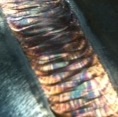
Had a rush job today. Customer needed these DOM tubes welded for something used in the Frack industry. The only catch in these welds was I had to get the weld as close to the edge of the tube without to much of it off. Was a fun little job. I love using the rotisserie!
-Jonathan
I got all 12 of them done. Was a good easy job, wish more like this would show up! My wife was out there taking pictures of me and she did not believe me when I said I would post them here. Here is proof that I do get to weld once in a while.
Oh and a real weldor wears pokadot beanie.
-Jonathan
For those who want to know what I do at my day job, here it is. Our patent was published a few months ago and we are realeasing these videos to the public so now I can share. This has been a 5 year project thus far and will have a couple more years until everything is completely done. The machine pictured is designed to be used in mainly tunneling applications but we will be also targeting open trench as well. We built everything on the machine from a pile of steel and had machining done elsewhere. In its current state it will push 30" 3/4" wall pipe for 5 miles up a 2* incline, generating 1.2 million pounds of max thrust. A complete stroke takes less than 3 minutes, so our hold up is the welding. The clamping system can be changed to accept 8" up to 42" pipe. The rollers I posted earlier in this thread can be seen in the first of the video. I am in the middle of designing a welding station to incorporate orbital welding to increase production and allow the machine to operate efficiently. Soon I will post actual pictures of the machine as it is a little different than the video. There are clamps at both ends in real life, not one. Anyway thought I would post this up. http://www.youtube.com/watch?v=jEKh_FrPM7E
-Jonathan
Last edited by Superiorwelding on Sun Jun 29, 2014 10:25 am, edited 1 time in total.
Kinda bored today so we started in on our 3G mig. Only picture I took but good reference anyway. This is the second pass. Specs; Pulse on 350MP .035 ER70S-6, 90/10 gas, 165 WFS, .96 trim. Runs like a champ.
-Jonathan
Might as well put this up too. Trying out my Cougar pistol gun and loving it! Here's the best I have do far. Won't bore on specs as there are to many for this. Feel free to advise how it can be better.
-Jonathan
Thanks, I should have paid better attention to the 3F part and I would have not asked about the weave
Looking good, are you certifying now or just practicing?
-Jonathan
Part of my weld to australian standards module for my cert 4
Was very pleased with it.
Shame iPhone4 takes average pix.
Messed around yesterday with some 7018.
Only really done arc to help other students once my module was done, so was time to Prac on 3/8 in 1g again with a 3/32 open gap and land.
Slowly getting better
Superiorwelding wrote:For those who want to know what I do at my day job, here it is. Our patent was published a few months ago and we are realeasing these videos to the public so now I can share. This has been a 5 year project thus far and will have a couple more years until everything is completely done. The machine pictured is designed to be used in mainly tunneling applications but we will be also targeting open trench as well. We built everything on the machine from a pile of steel and had machining done elsewhere. In its current state it will push 30" 3/4" wall pipe for 5 miles up a 2* incline, generating 1.2 million pounds of max thrust. A complete stroke takes less than 3 minutes, so our hold up is the welding. The clamping system can be changed to accept 8" up to 42" pipe. The rollers I posted earlier in this thread can be seen in the first of the video. I am in the middle of designing a welding station to incorporate orbital welding to increase production and allow the machine to operate efficiently. Soon I will post actual pictures of the machine as it is a little different than the video. There are clamps at both ends in real life, not one. Anyway thought I would post this up. http://www.youtube.com/watch?v=jEKh_FrPM7E
-Jonathan
Impressive!
It seems to be based on current "line-bore" technology for pushing small-bore pipe and conduit under obstacles, but done "on steroids"!
Steve,
You are correct. It's basic structure comes from directional drills. If we added the gear box we could drill with it as well. I will get a few pictures of the actual machine soon.
-Jonathan
Edit; here is a pic of most components on the machine. At this point there was alot of hydraulics, wiring and assembly left.
Superiorwelding wrote:Steve,
You are correct. It's basic structure comes from directional drills. If we added the gear box we could drill with it as well. I will get a few pictures of the actual machine soon.
-Jonathan
Edit; here is a pic of most components on the machine. At this point there was alot of hydraulics, wiring and assembly left.
Are some of the weldements in these pics, resemble those cracked welds in your first posts??
Just a couple welders and a couple of big hammers and torches.
Men in dirty jeans built this country, while men in clean suits have destroyed it.
Trump/Carson 2016-2024
John,
You are correct. The thread "cracked welds" did indeed come from the end clamps seen in those pictures. There are still imperfect welds but thankfully they are noncritical in nature. Also in the design we kinda went overboard on strength requirements. Some will in fact need repaired as we are beginning the process of certifying this machine and what a monumental task that is!
Here is one of the cracks from that thread that I actually repaired.
-Jonathan
Here is another project we did about 2 years ago. It is a Recycler used in drilling, slurry walls, vertical shafts and other fields. It is made to ISO container specs so they can be shipped like a regular shipping container. The bottom holds the pumps, motors and fluid, while the top has the shakers and hydrocyclones. It is the only one like it in the world to date. We designed it for a very quick set up and tear down as opposed to others that take a very large foot print at a job site. It is literally plug and play. This machine was shipped to Sourh America for use at our parent company.
-Jonathan