What welding projects are you working on? Are you proud of something you built?
How about posting some pics so other welders can get some ideas?
Post Reply
Martin Site
  • Posts:
  • Joined:
    Thu Nov 27, 2014 2:40 pm

I'm making a welding table similar to this. Frame is already done. Dimensions are 70"Lx34"W with 3x2x1/4w tubing

Image
http://www.garagejournal.com/forum/show ... 45&page=2
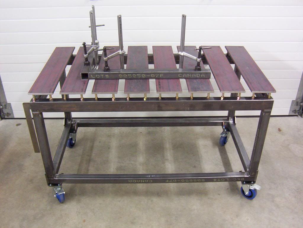
I originally wanted to copy his design except counter sink allen head tapered bolts into the plate, tap threads into the tube, and have them adjust the plate up and down with jam nuts rather than weld the bolt head on the backside of the plate and hole saw tons of holes into the tubes for adjustment access.

Thing is, in his post he says the 1/2 plate is more rigid than I found out. It's also not flat. I grabbed a piece at work and pushed down on it with 1 hand across a 25" span and could see lots of flex. So my next idea is to use channel, but it would probably make clamping quite difficult. Rectangle tubing 2x6 I am considering also. Has to be flat and rigid.

Any ideas? I work as a fabricator by trade at a shop so I have access to lots of options for material.
User avatar
  • Posts:
  • Joined:
    Thu Jan 24, 2013 10:13 pm
  • Location:
    Eddy, TX

Martin,
First welcome to the forum! That is a nice table there for sure. I advise against C-channel for the following reasons, it is not flat by any means, the tolerances on channel can mean your legs might be longer or shorter and clamping would be rather difficult. If you want plate like shown I would go with cold rolled. Cold rolled will be stiffer than the hot rolled in the picture and it will be flatter and true. Get us some pics of your table project!
-Jonathan
Martin Site
  • Posts:
  • Joined:
    Thu Nov 27, 2014 2:40 pm

Leg/flange length is irrelevant as it will be lifted off the table. Price is a major consideration
User avatar
  • Posts:
  • Joined:
    Thu Jan 06, 2011 11:40 pm
  • Location:
    Near New Orleans

Welcome, Marten Site!

It took me a minute, but do you have a cousin named Austin Knight?

I love clever screen names.

I like the general design of the table you posted. I'd personally follow the original design, with the addition of stiff-backs on the 1/2" plate. 2" by 1/4" flat stock stitched perpendicular along the centerline will make that 1/2" incredibly rigid without impeding your clamps.

Two cents...

Steve S
Martin Site
  • Posts:
  • Joined:
    Thu Nov 27, 2014 2:40 pm

I didn't think many people would catch on to the name :D

That's the kind of practical and simple idea I was looking for. I had my mind so focused on a material type that I didn't consider other options. I'll C-clamp to a big piece of flat tubing and stitch it in with minimal amperage and see what happens. Hoping it doesn't want to potato chip even a little.


People who ask me what I'm doing think I'm over-engineering a simple table but I think not. Taking a little extra time to make a perfectly flat table with unlimited clamping possibilities sure makes building things more enjoyable and quick.

Going to use flat head socket screws that will be countersunk with a slice of round bar with a tapped hole in it TIG'd to the bolt on the backside of the surface plate to keep the bolt head below the surface but still allow for rotation and adjustment.

Image

I'll share the pictures as I finish it. Legs are removable/height adjustable.
jwright650
  • Posts:
  • Joined:
    Wed Dec 03, 2014 3:27 pm

Otto Nobedder wrote:Welcome, Marten Site!

It took me a minute, but do you have a cousin named Austin Knight?

I love clever screen names.

I like the general design of the table you posted. I'd personally follow the original design, with the addition of stiff-backs on the 1/2" plate. 2" by 1/4" flat stock stitched perpendicular along the centerline will make that 1/2" incredibly rigid without impeding your clamps.

Two cents...

Steve S
I chuckled out loud when I read that screen name the other day... :lol:
John Wright
AWS Certified Welding Inspector
NDT Level II UT, VT, MT and PT
NACE CIP Level I Coating Inspector
Martin Site
  • Posts:
  • Joined:
    Thu Nov 27, 2014 2:40 pm

2.5 months later and I'm finally making progress. Had to move houses and now have a garage 4x the size of the last.

I have all the plates and the table frame finished. Went with 1/2" plate with stiffeners stitched to the bottoms. Just waiting on the bolts to arrive. Here's the design that will allow 4 point adjustment on each plate like the previously mentioned design that inspired me except more simplified and less work to implement.
welding table plate adjustment bolt
Untitled.png (8.15 KiB) Viewed 3012 times
The bolt will spin freely in the plate and will be sunk into the surface. A jam nut will be used to lock the adjustment down but wasn't included in the diagram for easier interpretation.

I used 3x2x1/4w tubing for the table frame with removable/adjustable/leveling legs so that I can hang the table flat on the wall when I'm not using it.

Also going to cut slices from some round stock and make pucks that clamps can be welded or bolted to so they can slide across any of the slots. Like this :
Untitled.jpg
Untitled.jpg (17.01 KiB) Viewed 3011 times
Expect updates and pictures very soon.
Martin Site
  • Posts:
  • Joined:
    Thu Nov 27, 2014 2:40 pm

Progress. Table just needs tapping nextImage Image
Drifta-X
  • Posts:
  • Joined:
    Mon May 26, 2014 2:53 am
  • Location:
    Melbourne Australia

The free spin bolt idea is flawed, sorry.
Think about when u bolt it down or remove. 1/4 turn on each bolt One after the other type situation occurs

Also, since your frame has no cnr bracing I would suggest height adj casters to level your table out on uneven ground.
And all ground it un even lol.

Other then that keep up the good work!!
I have a soldering iron!
Martin Site
  • Posts:
  • Joined:
    Thu Nov 27, 2014 2:40 pm

I'm not sure how the 1/4 turn deal means it is flawed. that is by design.

The legs/bracing of the table is not complete. However, the legs do have adjustable feet. If the table flexes under testing I will stiffen it. 1/4"w 2x4" tubing, so that may not happen.
Martin Site
  • Posts:
  • Joined:
    Thu Nov 27, 2014 2:40 pm

Drifta-X wrote:The free spin bolt idea is flawed, sorry.
Think about when u bolt it down or remove. 1/4 turn on each bolt One after the other type situation occurs
Not sure I quite understand you but I did drill and tap 4 holes for a single plate as a test and it worked perfectly. LIke you said and like I assumed, 1/4 turn per bolt before it tightens up under the plate's resistance to flex was true. But at 13 TPI it only takes 3.25 turns to go through the 1/4"w tubing.

I'm glad I did a test before welding the nuts to the bolts because the plates can be adjusted up and down to desired height and then the nut can be tightened against the plate to prevent the bolt from spinning, therefore locking the plate to that height. That didn't occur to me until testing because I'm a dumbass. This means the bolts can be replaced with taller ones if needed without cutting them off.

I'm gonna go drill and tap the rest of the holes, add folding legs, paint, and report back in the projects forum with the completed build.
Post Reply