What welding projects are you working on? Are you proud of something you built?
How about posting some pics so other welders can get some ideas?
wquiles
  • Posts:
  • Joined:
    Wed Sep 25, 2013 6:00 am

Here is my second welding project (first one was my welding table http://forum.weldingtipsandtricks.com/v ... f=9&t=3816).

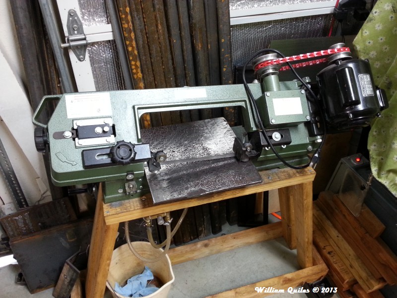
I have had this HF 4x6 probably since 2007 or so. Right when I got it, I discarded the flimsy folding "legs", and made a wood base for it. I later added a hydraulic piston to replace the spring, and for the most part that has been it until last fall (2013). But now that I am starting to do/learn more welding, and cutting metal more often, I decided to "attack" the many weak points, including the over-heating motor (which is obviously too small for the job - some of these actually catch on fire!). I also wanted to add cooling to it, so I decided to do a complete overhaul of the bandsaw. This took about 3 months (on and off), and several purchases spread over the 3 months (I am on a budget, like most people), but now that it is 99% complete, I wanted to share my project.

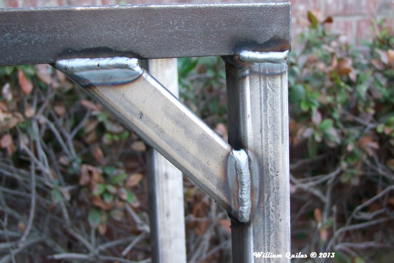
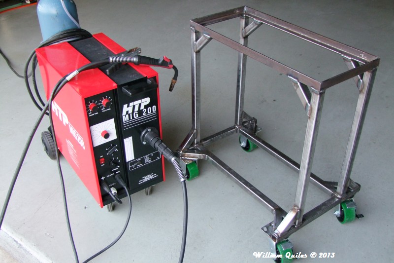
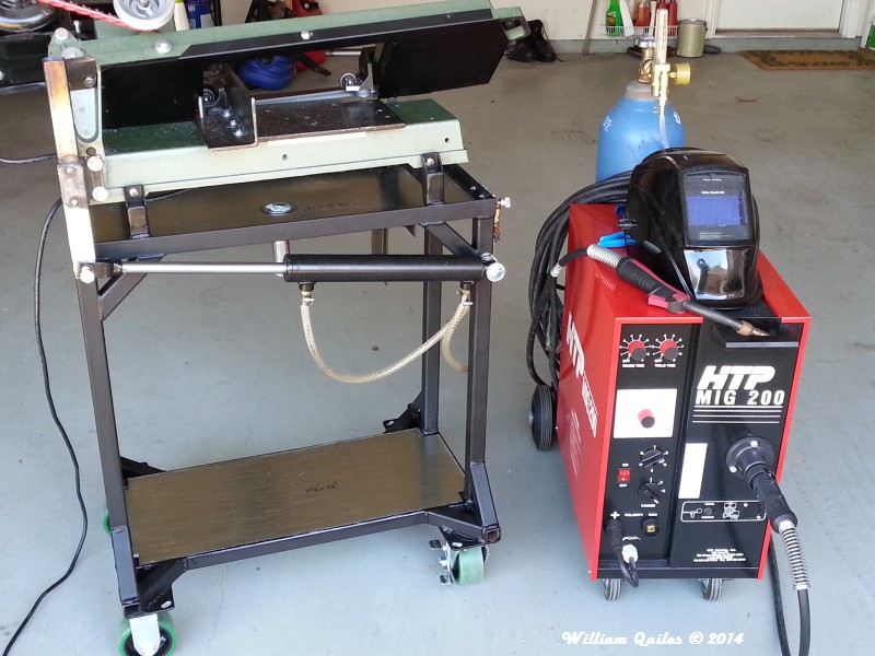
I of course over-built the base/stand, but I figured I can fairly easily re-use the base with another bandsaw if this one totally needs a replacement later on. I used 1-1/4" (1/8" wall) squared hot rolled steel, and 1-1/4" (1/4" wall) angle iron for the top. Everything was MIG welded with my MIG200 using 0.035" solid wire with about 25cfpm of 75%/35% shielding gas.

I literally have over 100 pictures, so over the next few days I will pick-n-choose some of them to show the progression towards the end product you see below.

Here is the "before" picture - I am checking the size of the new top (notice size of stock motor):
Image


Here is the "raw" new welded base:
Image


Previous wood base next to new base:
Image


Preliminary picture showing the hydraulic piston in place:
Image


Finished bandsaw after all mods:
- new steel base (2 coats of flat black paint)
- replaced 1/3 HP (Chinese rating!) SP motor with USA-made, Baldor 3/4HP 3P motor (using TECO VFD for variable speed and safety switch)
- new clamping "system" (more on that later)
- making new "arm" for hydraulic system
- adjustable coolant system (running
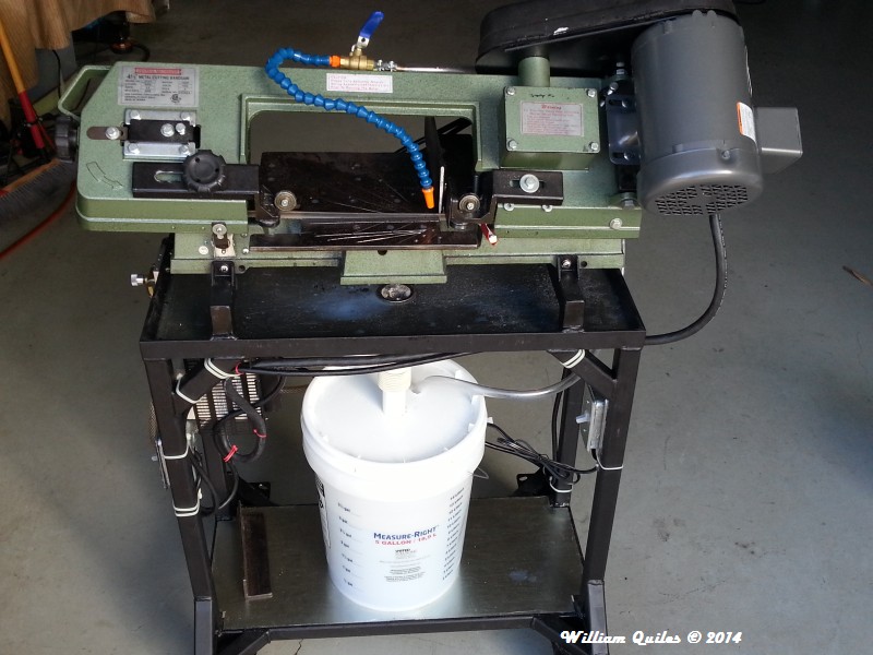
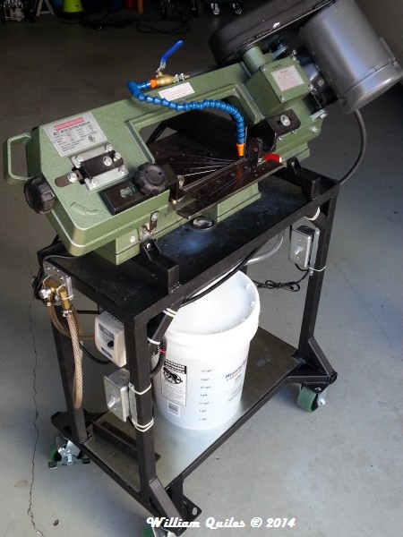

Image

Image


Will
User avatar
  • Posts:
  • Joined:
    Thu Jan 06, 2011 11:40 pm
  • Location:
    Near New Orleans

Nice!

How's your present investment (not figuring labor and/or enjoyment) compare to, say, a used TennSmith saw of similar size?

Steve S
wquiles
  • Posts:
  • Joined:
    Wed Sep 25, 2013 6:00 am

Otto Nobedder wrote:Nice!

How's your present investment (not figuring labor and/or enjoyment) compare to, say, a used TennSmith saw of similar size?

Steve S
Steve,

That is a tough question, since I almost always will fix/repair rather than replace. It has been so long since I got the original 4x6, that I have no idea how much I paid for it - maybe $200ish on special?

I then spend 3 months slowly buying parts for this upgrade:
Costs (of course not all bought at once!):
- Motor and VFD - about $220
- Coolant system - about $60
- Steel for the stand - about $50
- Premium casters - about $80
- Miscellaneous - about $40

So added up would be about $650 invested (including the original saw).

I honestly though/considering selling this "base" bandsaw and buying one "close" to what I wanted, but only used ones came close. In the end, since I "know" the history on this saw, and I cherry picked components for the upgrade over time, I decided to upgrade this one a little bit at a time (thus the 3-months to slowly buy parts/components) rather than buying something unknown with potentially additional expenses.

PLUS, I am learning to weld, so I "wanted" to build the stand from scratch. It was a great learning experience ;)

Will
User avatar
  • Posts:
  • Joined:
    Thu Jan 06, 2011 11:40 pm
  • Location:
    Near New Orleans

Sounds like a good deal in the end, for the experience as much as the knowledge of the components. The price isn't a problem as I see it, either, for the knowledge you have of the quality of what you've changed and added, versus what you'd spend for an "unknown quantity", as you pointed out.

Steve S
User avatar
  • Posts:
  • Joined:
    Wed Oct 23, 2013 3:30 pm
  • Location:
    Palmer AK

nice work ;)
Just a couple welders and a couple of big hammers and torches.

Men in dirty jeans built this country, while men in clean suits have destroyed it.
Trump/Carson 2016-2024
wquiles
  • Posts:
  • Joined:
    Wed Sep 25, 2013 6:00 am

A little bit more background on the "why" I upgraded the bandsaw with a hydraulic piston, since this is a popular mod for 4x6 bandsaws .....

The stock bandsaw comes with this stupid spring, which is meant to "try" to counterbalance the weight of the horizontal mass, in order to "try" to control how fast that mass (and thus the blade) moves down. You basically have a screw that you move in and out to change the tension on the spring against the moving mass. The problem is that it is nearly impossible to get the spring to perfectly balance the weight AND control how fast the whole assembly moves down. Bottom line: the spring does not allow fine-tuning the speed to accommodate a variety of materials.

The hydraulic piston controls how fast the whole assembly moves down, by letting hydraulic fluid slowly escape via the adjustment valve. You can also completely stop the movement at any position along the travel angle, which comes handy to align the cut with the blade. This adjustment made available by the valve is "very" wide, thus you have almost infinite control on how fast the blade moves down into the work, so that you can adjust to the material type, thickness, number of pieces being cut, etc.. This flexibility is why ALL of the larger bandsaws have a hydraulic piston on them. The 4x6 don't have one (and have the stupid spring) not because it is not needed, but because cost - it is the only way to keep the saw cheap and available to the hobby machinist. Here are two Grizzly bandsaws showing a hydraulic piston on them:
Image

Image


These videos I took 3-years ago, but clearly show the adjustment range I have in my bandsaw:
- Video 1: This is the fastest down travel, fully opening the valve very fast. It you watch closely, you can clearly see the speed increasing as I open the valve:
http://www.youtube.com/watch?v=c6imAX3KnQ4


- Video 2: This is a slightly slower down travel speed. You could probably cut wood this fast, or a thin walled metal part:
http://www.youtube.com/watch?v=NEVeIn5Bv2Y


- Video 3: This is an example of a very slow, controlled downward speed obtainable with the hydraulic piston. This range of speed (or a tad faster) is typically what I use when cutting most metals:
http://www.youtube.com/watch?v=u-TpwCDG_5k


If you look at the 4x6 Yahoo group, you will see that this hydraulic conversion is one of the most popular upgrades. Lots of ingenuity in how folks have added a hydraulic piston to their 4x6 bandsaw, and it was from that group that I got the idea to do mine back 3 years ago.

Will
User avatar
  • Posts:
  • Joined:
    Thu Jan 24, 2013 10:13 pm
  • Location:
    Eddy, TX

WOW! I have one of these HF band saws in the garage and will never look at it the same again. I never even thought of upgrading it the way you did. Looks great. I do wonder what TPI blade you use. I think I have 10ish TPI on mine but it has been a long time since I bought blades. I had been getting my blades from HF and have been fairly impressed with them. I do not do much with it so they seem to last a while. When they go they usually break at the weld. Have you found a better blade or do you use the HF ones as well? Now I might have to modify mine as well!
wquiles
  • Posts:
  • Joined:
    Wed Sep 25, 2013 6:00 am

For the new base and clamping "system", I wanted to be able to hold stock at 45 deg on both sides of the blade. The stock system/clamp of course can't do this, so I gave up on it, and went to a simple model where (similar to welding) I just clamp the piece to the base. It is more work, and much slower, but I can now do things I could not do easily before. So not an "improvement", just a different way of holding stuff being cut. In fact, I did this first, and cut every single piece for the new stand using the new "system".

The new base started life as a scrap piece, 3/8" thick:
Image


After removing some of the high points in the mill:
Image


I started cutting it to "fit" - the idea being that it had to extend past the current "base" in order to allow me to clamp pieces to be cut to this new base:
Image


Fast forward to having everything drilled and tapped:
Image


I then started work on the first of two fences (one for each side of the blade):
Image


After some more work, and drilling and tapping, I now have one of the two fences ready:
Image


I then cut the fence flush, and allow the blade to go through the surface of the base, without going completely through it:
Image

Image


Now, to align that fence, I align it to the cut/groove on the base:
Image

Image


So now to cut something, I camp the piece to the base, using the fence for alignment:
Image

Image


Or use another piece of angle iron to clamp the piece to be cut to the rigid fence (similar to the stock clamping system):
Image


I then worked on the other fix fence, for the other side, which will only be used to make 45 deg cuts:
Image


With the hydraulic piston, I can get the blade to within a small distance of the piece, and measure accurately:
Image

So using the new "system", I cut the pieces, and checked the basic design by stacking the pieces - surprisingly it could stand on its own!
Image


Since the casters were going to be offset, I added re-reinforcements to the design:
Image

Image


Since the design I came up with had the weight of the bandsaw not aligned with the main support, I also added reinforcements there:
Image


And since I can now cut accurate 45 deg, I prepared all of the pieces:
Image

Image


So I then started to clean up, prepare, bevel, etc. all of the LEGO pieces:
Image

Image

Image

Image

Image


As with my prior project, I practiced and fine-tuned the MIG200 settings with the same size pieces I was going to be welding:
Image

Image

Image

Image


I actually measured the approx. wire speed to have an idea on where to start:
Image


I then started to weld (finally!):
Image

Image

Image

Image

Image


After grinding (to allow welding of other parts, casters, etc..
Image

Image

Image


That LED light that I made, that I showed earlier works great. Here is the before and after photos, with and without it:
Image

Image


More welding:
Image

Image

Image

Image

Image


Basic frame is complete:
Image


I then started work on the two "arms" that hold the bandsaw above the drain:
Image

Image

Image

Image

Image

Image


So now I have the two arms ready:
Image


After grinding:
Image


This is why I have that bevel cut on the bottom (facing the angle iron):
Image


To weld them, I added some "weight" I had laying around, which keeps them aligned and flat:
Image

Image

Image

Image


I then made (from scrap pieces) the "ears" which will bolt to the actual bandsaw. If I ever have to replace the bandsaw, these would be the ones to cut away and make new ones to fit the "new" bandsaw, thus reusing most of the base/stand:
Image

Image

Image


And after grinding:
Image

Image


Test fit:
Image


Then drill the holes in the ears:
Image

Image


Then I moved to "make" an arm, that would tie the upper bandsaw assembly to the base/stand. But I wanted something stronger, since it has to be offset a couple of inches outward. In order to make sure I would not crack the arm, I came up with an additional bolting point:
Image

Image


I also wanted this new arm to be removable, so it is offset backwards a little:
Image


This was all done with basically scrap pieces:
Image

Image

Image

Image

Image


I then welded the extended piece which ties to the hydraulic piston:
Image

Image

Image

Image

Image


Final "arm":
Image

Image
wquiles
  • Posts:
  • Joined:
    Wed Sep 25, 2013 6:00 am

Superiorwelding wrote:WOW! I have one of these HF band saws in the garage and will never look at it the same again. I never even thought of upgrading it the way you did. Looks great. I do wonder what TPI blade you use. I think I have 10ish TPI on mine but it has been a long time since I bought blades. I had been getting my blades from HF and have been fairly impressed with them. I do not do much with it so they seem to last a while. When they go they usually break at the weld. Have you found a better blade or do you use the HF ones as well? Now I might have to modify mine as well!
Forgot, as to the blade, I am using:

64 1/2" x 1/2" x 14T Bimetal Bands $13.41 each

An I ordered them from (no affiliation):

Kenny Schmidt
Industrial Saw & Grinding, Inc.
3920 Rufe Snow Dr.
N. Richland Hills, TX 76180
(817) 284-7416
Industrialsaws@aol.com
www.industrialsawandgrinding.com


Will
User avatar
  • Posts:
  • Joined:
    Wed Oct 23, 2013 3:30 pm
  • Location:
    Palmer AK

EXCELLENT :shock: :shock: :shock:
Wanna sell it ;)

John
Just a couple welders and a couple of big hammers and torches.

Men in dirty jeans built this country, while men in clean suits have destroyed it.
Trump/Carson 2016-2024
User avatar
  • Posts:
  • Joined:
    Fri Apr 01, 2011 10:59 pm
  • Location:
    Australia; Victoria

Hey,

You sure gave the photo upload a battering on that post... Good jub though, fine work on your new work table.

Mick
wquiles
  • Posts:
  • Joined:
    Wed Sep 25, 2013 6:00 am

For the VFD, following my mentor's advice, I put it away from swarf, but I also wanted an external enclosure to protect the unit and wiring. I found a scrap metal box in my "shop", which was almost the right size:
Image

Image


I then made a steel support for it:
Image

Image

Image


The box bolts to the support "T" with two bolts (and silicone in between), and the VFD bolts to the box at 4x places:
Image

Image


This whole assembly is then welded under the pan, ensuring that the VFD/electronics will remain free of debris and coolant:
Image

Image


I then gave everything two coats of flat black paint:
Image

Image


For the pan, I used galvanized steel, which I cut to size, to fit inside the angle iron top:
Image


I then applied silicone to the whole thing, to ensure a good seal - no screws needed - the surface tension along that much surface area is more than plenty:
Image


I then applied weight in the middle, to bow down the metal, thus ensuring coolant will flow towards the middle:
Image


After the top dried, I went back and applied another thick bead of silicone to make sure everything was plenty well sealed. I then moved to work on the bottom "shelf". Again, used galvanized steel, and epoxy:
Image

Image

Image

Image


I then moved to make the drain hole:
Image

Image


Siicone sealed on both sides:
Image


then found the perfect strainer for large debris:
Image


This is how it looked at that point in time:
Image


I then got another plumbing piece (with a larger inside diameter than the drain tube), to make the connection. The fit is such I can slide the white piece up and town to "make" the connection, thus allowing me an easy way to remove the 5-gallon if/when needed:
Image

Image


And after testing, it worked like I hoped (note the extra heavy silicone against the angle iron!):
Image


I even found use for the cap:
Image


And for those interested, this is the coolant I am using (at 10% concentration with distilled water):
Image
wquiles
  • Posts:
  • Joined:
    Wed Sep 25, 2013 6:00 am

Now that the electrical wiring is protected from coolant, I can assemble and wire the new VFD and 3-phase motor. I started by installing a grommet to protect the single phase power coming into the VFD:
Image

Image


Since I needed to have the right length for the 3-phase motor wire, I installed the new Baldor 3/4HP motor. Look how much larger it is compared to the "1/3" HP factory unit (would get so hot I could barely touch it!):
Image


I of course used the low voltage wiring as my VFD outputs 220V 3-phase:
Image

Image


Then tie everything together and test - I got lucky (50-50 chance) that the motor started turning in the direction I wanted!:
Image


I then wired the switch for the coolant pump (inside the 5-gallon, with the inlet a few inches from the bottom, so it does not suck in much debris), tie-wrap everything securely, and that is all:
Image


The only thing to note/add, is that the original ON/OFF switch on the bandsaw is now a logical signal to the VFD. The switch is re-wired as an E-STOP (emergency stop), so now I have an extra safety step to get the motor running, as it takes two steps:
- E-STOP has to be UP
- I can only start the motor by pressing the START/STOP button on the VFD (which is recessed on purpose, so nearly impossible to hit/press by accident).
- Moving this E-STOP switch UP will never start the motor, but it has to be up for the START/STOP on the VFD to work at all.


The small dial on the VFD (also recessed) controls the speed of the motor, so I never have to change belts again to adjust speed to material, thickness, number of pieces, etc.. The coolant switch is independent of the motor, so I can choose and adjust the output flow if/when needed.


Will
Wes917
  • Posts:
  • Joined:
    Fri Oct 25, 2013 11:45 pm

Very nice project, one nice saw you got there now
wquiles
  • Posts:
  • Joined:
    Wed Sep 25, 2013 6:00 am

Thanks. I have a couple of pending welding projects for this year, so the improved saw will come handy ;)

Will
hacadacalopolis
  • Posts:
  • Joined:
    Fri Jan 31, 2014 5:14 am
  • Location:
    pensacola, Fl

Bravo Wquiles!
I had planned on getting the HF horizontal bandsaw. The lesser of the two they sell.
It appears you have "Outdid" not only the stand, but the entire assembly. Looks like shop luxury!
Screw the KAMA, Your build for the win. Would love to see a video of it running.

Very nice cuts with your base mod. How much different is the precision of a cut made like you have now vs stock cutting angles on the machine?

Also, where did you get your C-clamps? ( low profile face), The one with the longer tongue on it?
wquiles
  • Posts:
  • Joined:
    Wed Sep 25, 2013 6:00 am

hacadacalopolis wrote: Very nice cuts with your base mod. How much different is the precision of a cut made like you have now vs stock cutting angles on the machine?
Better than I expected. While testing, I cut this piece, which game a nice, small, right triangle:
Image

Image


I lightly filled the edges, and when I compared to my machinist square, it was a dead match to it:
Image


But that is also because the alignment is done with a very large drafting triangle, along the channel the blade cuts over 12" in length, so although slow to setup, it is not only accurate, but repeatable:
Image


hacadacalopolis wrote:Also, where did you get your C-clamps? ( low profile face), The one with the longer tongue on it?
HF - Chicago Electric Welding - Item#65683. Cheap, but work well enough so far:
http://www.harborfreight.com/12-inch-he ... 65683.html
hacadacalopolis
  • Posts:
  • Joined:
    Fri Jan 31, 2014 5:14 am
  • Location:
    pensacola, Fl

I'm so envious. Very nice cuts. So precise!
I will definitely be referring to this thread as I will be purchasing that horizontal bandsaw along with those clamps- Btw, I cannot believe I haven't seen those...I am up there all the time, so much so I'm surprised I don't work there. Maybe my store doesn't carry them. I'll have to look harder.
Cricket
  • Posts:
  • Joined:
    Tue Aug 20, 2013 10:49 pm
  • Location:
    Oregon, WI

So much work... watch out for the gear box. They like to strip the teeth wich makes the whole thing worthless. As well as the bearings on the main wheels. My personal experience... :evil:
wquiles
  • Posts:
  • Joined:
    Wed Sep 25, 2013 6:00 am

Cricket wrote:So much work... watch out for the gear box. They like to strip the teeth wich makes the whole thing worthless. As well as the bearings on the main wheels. My personal experience... :evil:
Excellent point, as those are two known weak points. One of the first things I did when I got the saw was to replace the nasty gunk that was inside the gear box with a premium lube. That was back around 2007 and the saw is still performing like new today. Now, the bearings on the main wheels, yup, those I will have to change/replace once they die - I till try to use better quality replacements when that happens. Thanks for the heads-up/reminder on these ;)

Will
bandaidmd
  • Posts:
  • Joined:
    Tue Feb 11, 2014 5:01 pm
  • Location:
    Maryland part of Delmarva

SAW 2.jpg
SAW 2.jpg (61.28 KiB) Viewed 7242 times
SAW.jpg
SAW.jpg (54.69 KiB) Viewed 7242 times
Seeing Mr. Quilas beautiful job on his bandsaw motivated me to also make some mods to mine.
I braced up the rickety stock base a long time ago and mounted it to a roller platform and it works for me so I will keep it the same.
I really liked the front table so i added one with a fence, both of my fences have threaded locater holes at 90 and 45 , anything between will be clamped in place. It goes without saying the front fence will only get used for that reverse/oddball angle you cant clamp in the back.
The larger rear platform let me extend the stationary fence and the hold down fence, the 1/2 holes will hold a piece of threaded rod as a spreader for clamping shorter work.
The awkward clamping on these machines made me use it more vertical than horizontal but i think it will be much easier to use now.
Next will be a hydraulic downfeed (once i get over the sticker shock). The ones i see on ebay are $90 ,anyone have a cheaper solution?
wquiles
  • Posts:
  • Joined:
    Wed Sep 25, 2013 6:00 am

bandaidmd wrote:
SAW 2.jpg
SAW.jpg
Awesome :D
Post Reply